Wednesday, 14 August 2013

Fitting the gearbox mount

One of the next jobs we could get on and start doing was fitting the gearbox mount. This is a rubber shoe that fits in the little bracket in the middle of the car. Unfortunately its not just a blot on job and needs some modifying in order to fit in the hole. 

Tools you may need for this job;

Hack saw
Drill with corresponding drill bits to fit the supplied bolts
measuring tools 
Polyurethane  sealant (optional)
Steady hands

The gearbox mount is a funny little rubber shoe that needs to be fitted in order to sit and locate the gearbox position. When you buy a gearbox mount unit it will not fit directly into your chassis bracket. This is because it is from a Sierra and still has the old mounting holes drilled. To modify the mount we placed the unit on top of the bracket. The mount did not sit flat with the bracket. Instead the old lugs where balancing themselves on the two opposite chassis cross members that emerge from the bottom of the tunnel. 

We marked where the lugs caused interference and cut them off with a hacksaw. This now sat snug.
We then needed to know where the four new holes where going to be placed on the mount. To align this we needed to move the gearbox into position.

We used our engine crane and some straps to align it up with the prop shaft.
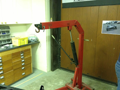
Getting the Crane ready for lifting

    
Lining the gearbox up with the propshaft
Easy does it


Once the gearbox was in place we bolted it to the prop shaft with the three heavy duty bolts and spring washers. They where tightened all the way up so we knew the gearbox couldn't slide anymore forwards or backwards. Now it was time to mark the holes for the gearbox mount. We slid the mount underneath the bracket and lined it up with the gearbox foot lug (a beveled piece of steel that bolts onto the bottom of the gearbox, shown in the image below). Once here drill points were marked onto the mount and the gearbox was taken out again. 
     

With these points now marked the mount had the four holes drilled and filed out. It was now time to be fitted. The mount was placed underneath the bracket and bolted on using the bolts provided in the kit. Finally Some polyurethane sealant was used around the edges of the mount to seal the unit in place.    


Underside of the car, showing the bottom of the mount poking through

Friday, 2 August 2013

Brake calipers


For our cars callipers we decided to be adventurous. Before we purchased them I (Tom) did some research into what callipers where available for our type of setup. Naturally the first thing that came into my head was BREMBO! After seeing the classic red coloured callipers on high performance cars I thought I may as well see what sort of pricing it would be for a pair. I then found out that Brembo do not sell their callipers right out the box, they are fitted to performance cars that roll out of the show room. Armed with this new knowledge I hunted Ebay for a bargain, looking for callipers that had been pulled from old 406 coupes or alphas. A few came up but breakers were asking £400-500 for a pair of second hand ones. I also found out that they all have different brackets and may not suit my setup.

I did find some nice black callipers from and old e36 to suit sierra brackets. The only problem was that the minimum wheel size they would fit would be 17". This restricted our wheel choice so I had to have a re think.

In the end we opted to go down the route of the sierra cosworth rear callipers and standard sierra fronts. When we bought them they where covered in a gold electroplate finish. While this was fairly nice I didn't really stand out and wouldn't be noticed behind the wheel. Following our yellow and chrome theme we had the bright idea to paint them yellow. I trekked down to Halfords and picked up some yellow calliper paint. The brakes where disassembled and we began coating it. After 3 coats of paint the calliper looked O.K. the problem with the paint was if you accidentally re stroked it in the same place it would drag and when it dried smear marks could be seen. Another thing to note was the paint compound was horrible, it dried up into strings on your brush and didn't come out in white spirit. Fearing the paint would clog up our spray gun we opted to find someone who could paint them with a professional finish.

After a quick search on the internet we found a company called brake calliper specialists down in nottingham. This company specifically deal with refurbishing and painting callipers for many different types of vehicles

We sent them off to be painted. When they where delivered back to us to looked stunning, well worth it

We un boxed them and fitted the brake pads inside the callipers. This was easy for the rears, they just slot and clip in either side. The springy clip on the pads keep them in position.

A week away.....

My dads off on a cruise so its just me, the car and my common sense

Fitting the callipers was not that hard of a job. The discs were pushed onto the hubs and secured with a wheel nut while I aligned the brake onto the bracket. There are only two mounting bolts which screw and secure it in place. The problem I was having was that the actual calliper was not sitting dead centre over the disc, and was therefore fouling it when it span. To resolve this I filed the bracket lugs so it could be aligned properly. I only took a small amount off, something like 1.5mm, but it was enough to centralise it. After it had been filed washers were placed between the lug and the calliper and it was central! This same process was used for the other side so that it sits nicely and doesn't rub on the disk.

The next job to do after the bolts where torqued up was to fit both the hand brake cable and the flexi hose.

The hand brake cable should enter the calliper from the top, going through a round hole near the spring. After you thread it though the square end of the cable needs to latch onto the spring hook. The cable will be P clipped to the hub carrier at a later date so its not waving all over the place when driving. Lastly the Flexi hose was fitted to the callipers. This routes from the brake pipe that is connected to the rear union to the underside of the calliper. There are two holes on the bottom, One with a nipple end and one with an allen key fitting. The allen key fitting needs to be taken out and the flexi hose screwed into the hole. The other nipple on the underside is a breather hole and should not be taken out.

Underside of the rear calliper