


 The idea would be to find a beat up set from either the reckless or ebay and get them refurbished. I ended up buying a set of 16s from ebay off an old scrapped mondeo. After getting these home I found that they were very large, especially with the chunky tires they came with.
  |
| Getting the Crane ready for lifting |
 |
| Lining the gearbox up with the propshaft |
 |
| Easy does it |


 |
| Underside of the car, showing the bottom of the mount poking through |


 Fitting the callipers was not that hard of
a job. The discs were pushed onto the hubs and secured with a wheel nut while I
aligned the brake onto the bracket. There are only two mounting bolts which
screw and secure it in place. The problem I was having was that the actual
calliper was not sitting dead centre over the disc, and was therefore fouling
it when it span. To resolve this I filed the bracket lugs so it could be
aligned properly. I only took a small amount off, something like 1.5mm, but it
was enough to centralise it. After it had been filed washers were placed
between the lug and the calliper and it was central! This same process was used
for the other side so that it sits nicely and doesn't rub on the disk.
Fitting the callipers was not that hard of
a job. The discs were pushed onto the hubs and secured with a wheel nut while I
aligned the brake onto the bracket. There are only two mounting bolts which
screw and secure it in place. The problem I was having was that the actual
calliper was not sitting dead centre over the disc, and was therefore fouling
it when it span. To resolve this I filed the bracket lugs so it could be
aligned properly. I only took a small amount off, something like 1.5mm, but it
was enough to centralise it. After it had been filed washers were placed
between the lug and the calliper and it was central! This same process was used
for the other side so that it sits nicely and doesn't rub on the disk.
 The hand brake cable should enter the
calliper from the top, going through a round hole near the spring. After you
thread it though the square end of the cable needs to latch onto the spring hook.
The cable will be P clipped to the hub carrier at a later date so its not
waving all over the place when driving. Lastly the Flexi hose was fitted to the
callipers. This routes from the brake pipe that is connected to the rear union
to the underside of the calliper. There are two holes on the bottom, One with a
nipple end and one with an allen key fitting. The allen key fitting needs to be
taken out and the flexi hose screwed into the hole. The other nipple on the
underside is a breather hole and should not be taken out.
The hand brake cable should enter the
calliper from the top, going through a round hole near the spring. After you
thread it though the square end of the cable needs to latch onto the spring hook.
The cable will be P clipped to the hub carrier at a later date so its not
waving all over the place when driving. Lastly the Flexi hose was fitted to the
callipers. This routes from the brake pipe that is connected to the rear union
to the underside of the calliper. There are two holes on the bottom, One with a
nipple end and one with an allen key fitting. The allen key fitting needs to be
taken out and the flexi hose screwed into the hole. The other nipple on the
underside is a breather hole and should not be taken out. |
| Underside of the rear calliper |

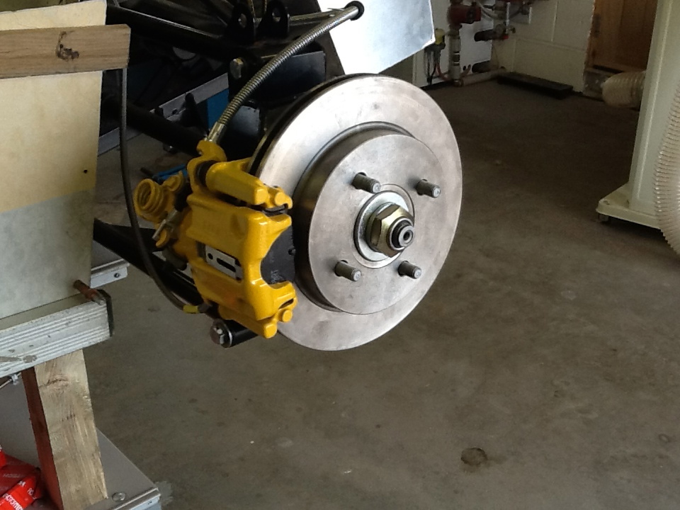
 To start this job we aligned the calliper mounting brackets against the hub carrier. Its fairly simple to know which one goes no the left and right. The lugs on the bracket that hold the calliper in place should be facing outward. So if I was looking at the nearside of the car the bracket lugs should face towards me positioned to the left of the hub if I was to look at it side on. The picture on the right may explain it a little better. Once the calliper bracket is in place offer the cylinder section of the hub around the drive shaft and line the holes up. One thing to note at this point, the hubs have one flat side and a rounded side. This helps you determine which was around it sits. The flat edge should be pointing backwards and the rounded edge forwards. You may be able to see on the smaller image that the flat face is facing to the back. Put you bolts in and tighten them up.
 The refurbished unit looked ace! finished off with a black spray paint, looked like it had just come from the factory. Paint was scraped off the flat edges ready for gasket fitting. Two things that we did have to find out were what the two holes in the box where for. The circular one at the front and the rectangular one in the middle. Turns out the circular one is for a taxi meter, for all the lotus 7 taxis that are running about. The square hole is for the reversing light. Our gearbox came with a plastic cover with two wires which we are hoping connect up to the loom.
  |
| Just need to pull the engine crane out the shed to align it with the mount. |
 |
| Supreme finish |


 |
| Finish product, looks pretty good |
 |
| We are now able to wheel the car around the garage, good job! |
 The front outlet runs from the master cylinder and under the steering column bracket. When it gets to the central tunnel we threaded it over the cross member and down the tunnel towards the rear of the car. We threaded the pipe under the hand brake bracket and towards the splitting union at the back.
 The offside brake pipe runs from the middle outlet of the master cylinder. We ran it parallel to the first up to where it crosses over the member. It then runs down the side footwell panel and across the front drivers panel making sure it doesn't run In front of the steering column hole. Lastly it runs down the side of the chassis and bends downwards where it meets the wishbone bracket
 |
| All 3 brake pipes running over the central cross member |
 |
| Offside brake line routing running from the middle outlet of the master cylinder. |
 |
| Nearside break pipe running from the bottom outlet of the master cylinder (yet to be P clipped) |
 Once the rear wishbones where on and in place we strapped them up and began wondering how the drive shafts connected to the differential. Because the Diff sits to one side there is a long and short shaft. Its easy to figure out which goes where, if you where to look at the car from the back the short one goes on the left and the larger on the right. Im pretty sure GBS label the drive shafts so you shouldn't have a problem.
 |
| Photo taken from the back of the car, both drive shafts are in place |
 However this was not the case, people where placing two on one side and none on the other. When we lined our wishbone up this was happening for us as well, on some brackets there was room for two washers on one side and none on the other and for other cases there was room only room for a washer either side.
 We tried to get a washer either side, which worked better now we had widened the brackets but there was still space in some areas where we could fit two. After chatting with GBS we where informed that it doesn't really matter where they where spaced, just fit them in where you can. So as best we tried, some places needed more and some places needed less.
 The first job is to sand all of the powder coat out of the wishbone ends. We clamped the wishbone n a vice and used an electric corded drill and several attachments to get it all out. We started with a very corse attachment and slowly progressed to a finer one and finally a round sandpaper piece.
 Before they where pushed all the way in we used the metal feral to make sure the bushes could not be pushed beyond the correct amount therefore avoiding the plastic to warp. The feral's had thier sharp edges filed down on the sanding machine before being lubed up and slotted into the hole.
 Upon setting the panel in place we noticed that the sheet of ally was sitting at an angle to the bar that runs across the top of the chassis. We investigated this matter further and found out that if we riveted the sheet to the chassis the ally would distort and create a pressed effect almost like the look of a press studded sofa, which looks messy and unprofessional. We measured the angle of the gap and cut a piece of wood to this degree and length. It was then stuck to the top bar using the black poly sealant stuff. Once dry the wood was sanded using a sanding belt to remove any sharp edges and to make it smooth.
 The ally was then placed back into position to see how it now sat. This time round it sat beautifully with no bend or play when it was pushed up tight against the chassis. After seeing how well this technique worked we used it to create 4 more pieces to fill in angled gaps between the two bars that run from the corners to the cross section that supports the top of the tunnel and the bottom of the rear floor pan.
 | |||
| Made an oopsy, the wood slipped down when drilling holes so had to re-drill. As you can see the angle inst huge but by using this spacer we avoided horrible warps in the metal like we have seen with other builds. |
 |
| Final rivets going in the sheet, looking good, metal looking as straight as an arrow! |