Saturday, 29 June 2013

The gearbox arrives!

Exiting times! We finally picked our gearbox up from GBS.
We opted to get the MT75 gearbox for few reasons over the type 9. 

Before we bought we did our research to see the differences and pros and cons of the different gearboxes available for our build. The two main competitors were the Type 9 and MT75. 

We picked the MT75 because it was "More reliable" as it comes from a Ford transit.
Lighter, weighing 7kg less than the type 9.
More torque, not that you'd need it from a 2 litre zetec but its nice to know it'l handle 300nm
And a synchronised reverse gear, for those times you want to impress the ladies with your J turn skills

One thing that the Type 9 does have over the MT75 is the fact that the innards can be changed with much more ease. This is good for people changing cogs over for different ratios on tracks. Seen as though the car would spend more time being cleaned than on a track this factor didn't really effect our decision. 

The refurbished unit looked ace! finished off with a black spray paint, looked like it had just come from the factory. Paint was scraped off the flat edges ready for gasket fitting. Two things that we did have to find out were what the two holes in the box where for. The circular one at the front and the rectangular one in the middle. Turns out the circular one is for a taxi meter, for all the lotus 7 taxis that are running about. The square hole is for the reversing light. Our gearbox came with a plastic cover with two wires which we are hoping connect up to the loom. 
Just need to pull the engine crane out the shed to align it with the mount. 
Supreme finish
     

Friday, 28 June 2013

Low pressure pump and fuel filter

One of the next jobs we completed was fitting the fuel pump and filter to the bracket behind the differential. We used a few different tools and techniques to GBS because it suited our method of thinking.

Things you may need for this job;

An array of drill bits suitable for drilling holes for the pump and possibly the fuel bolts.
Jubilee clips
Files
A spacer (to mount the fuel filter on)
Spray paint


Firstly we created a new ally bracket from the one that was supplied. The supplied sheet had pre drilled rivnut holes which we believe where used in older versions of the car where the pump and filter where screwed into the rivnuts. We opted to rivet a newly cut piece of ally to the chassis. We measured it up and spaced the rivets accordingly.

Holes for the fuel pump were drilled and it was assembled and mounted on the little rubber bobbins provided in the pack. Remember to use PTFE tape on the ends of the pump before you screw on the brass fittings, this will prevent any leaks.

For the fuel filter a small spacer was constructed to make it sit level with the pump. We didn't want it to sit on the ally because it meant putting a bend in the pipe and although this bend may not have restricted fuel flow the arrangement of the two components on different levels looked tacky.

The spacer was constructed from a piece of old oak. I found a large piece of this oak and cut a small section off to make into the spacer. It was then given 3 coats of black spray paint before being glued with the black poly sealant to the ally. Once glued holes were drilled through the top of the wood and through the ally to thread blots through, securing the adjustable plastic tie wraps around the filter.

Finally A piece of fuel pipe was cut to length and jubilee clipped around both ends of the two components.  

Thursday, 27 June 2013

I can't hold her captain, I DONT HAVE THE POWER!

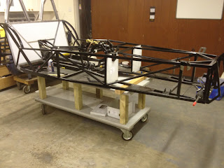
Sorry about the corny Ace Ventura title but I thought it was appropriate for my next post. We have been so busy adding components to the car we didn't realise what was happening to the car trestles. As we looked from the bottom we noticed that the stands where warping. The legs had become very bowed and they didn't look stable at all. The last thing we wanted was to hear a big crash in the night and the thought of our time and money smashing on the concrete floor.

We needed to resolve this problem fast. We decided to make a dolly out of some old bits that had been left in boxes for a rainy day. The idea that it would have wheels would enable us also to move the build  around the garage or rotate it so other areas could be accessed with more ease.

To build the dolly we used;

4 rotating wheels
2 pieces of old table top
6 pieces of wood
A handfull of bolts and screws

Firstly we fitted the wheels to the bottom of the table top.

We then screwed and bolted to wood to the top of the table.

To add strength we attached another old table top onto the top of the wood struts.

It was screwed together and there you have it.  

At a later date we decided to add some side struts between the upstanding wood, just incase it needed any extra support.


Finish product, looks pretty good

We are now able to wheel the car around the garage, good job!

Friday, 21 June 2013

Brake line routing

Brake line routing is one of the first jobs you can complete but should not be rushed. The fact that the brake lines will not be seen by anyone doesn't mean that they shouldn't be neat and tidy. Before I started to bend the brake lines I had a look at some other peoples attempts and lets just say I wasn't impressed. Obviously if your bending brake lines with your fingers they wont be perfectly straight but they should be neat and hug the chassis comfortably.

Things you may need for this job:

Brake pipes
Your thumbs (preferably strong ones)

(Optional/ may be required)
A pipe cutting tool
A pipe bender
Pipe flanger
DO NOT USE PLIERS!

To start we needed to know which pipes go where. We asked at the GBS factory and we found out Naturally we thought the two front outlets on the master cylinder went to near side and offside at the front and the one on the bottom to the rear. This was not the case and after consulting GBS we found out that the outlets connect as follows;

Front outlet of the master cylinder goes to the rear.
The middle outlet of the master cylinder goes to the offside
The back underside outlet goes to the nearside.

The front outlet runs from the master cylinder and under the steering column bracket. When it gets to the central tunnel we threaded it over the cross member and down the tunnel towards the rear of the car. We threaded the pipe under the hand brake bracket and towards the splitting union at the back. 

The offside brake pipe runs from the middle outlet of the master cylinder. We ran it parallel to the first up to where it crosses over the member. It then runs down the side footwell panel and across the front drivers panel making sure it doesn't run In front of the steering column hole. Lastly it runs down the side of the chassis and bends downwards where it meets the wishbone bracket
Finally the last nearside brake pipe runs from the bottom outlet of the master cylinder. Again we ran it parallel to the other two brake pipes up to where it bends over he cross member. We then threaded it straight, continuing across one of the middle members to the passenger side footwell panel. Once here it routes the same way as the offside pipe but in an inverted fashion. Across the passenger footwell panel and along the side of the chassis and bends down at the wishbone bracket.


All 3 brake pipes running over the central cross member
Offside brake line routing running from the middle outlet
of the master cylinder.
Nearside break pipe running from the bottom outlet of the
master cylinder (yet to be P clipped)


Monday, 17 June 2013

Fitting The Drive shafts


Once the rear wishbones where on and in place we strapped them up and began wondering how the drive shafts connected to the differential. Because the Diff sits to one side there is a long and short shaft. Its easy to figure out which goes where, if you where to look at the car from the back the short one goes on the left and the larger on the right. Im pretty sure GBS label the drive shafts so you shouldn't have a problem.


The next part is very simple, all you need to do is rub some lithium grease on the end going into the diff and slide the drive shaft through the hub carrier. Once the end is in the diff you may want to turn it and push it slightly so the teeth line up and connect. You will know when its in and properly connected because it will be harder to spin.

Rest the outer end of the drive shaft on the rim of the hub carrier until you fit your hubs. When you turn one of the drive shafts the other should turn in the opposite direction, this ensures both shafts are fixed in to the diff properly. 

Photo taken from the back of the car, both drive shafts are in place